

































As commercial-vehicle camera systems move from legacy analog links to higher-definition digital vision, the video connection has become just as important as the camera itself. Trucks, buses, and vocational fleets often need images that stay clear, stable, and responsive over long harness runs and in electrically noisy conditions.
That environment is a big reason many modern “automotive” (commercial-vehicle) camera links use LVDS video: a digital video connection built around low-voltage differential signaling.
What LVDS Video Technology is
LVDS (Low-Voltage Differential Signaling) is a method for transmitting high-speed digital data by sending complementary signals over a pair of conductors and having the receiver detect the difference between them (rather than measuring one signal against ground). In camera systems, “LVDS video” typically describes a digital video link that uses this low-voltage differential approach to move image data from a camera to an ECU, recorder, or in-cab monitor.
In automotive environments, LVDS is widely used because its low signal amplitude and differential structure help control electromagnetic emissions and improve resilience to interference. This is the core reason LVDS-style links are often discussed when engineers talk about EMI in vehicle camera systems. Analog Devices frames LVDS as an effective interface for robust in-vehicle digital video in its design note LVDS Offers Robust Video Interface for Automotive Applications *.
How LVDS Works (Without the Math)
Differential signaling and common-mode noise
An LVDS pair carries two opposite-polarity signals. If external noise couples into the cable, much of it appears similarly on both conductors (common-mode noise). Because the receiver cares about the difference between the two lines, that shared disturbance is largely rejected.
Why the “low voltage” part matters
LVDS uses a relatively small voltage swing. Smaller swings and balanced currents in a differential pair generally reduce radiated emissions compared with many single-ended approaches. Texas Instruments discusses this EMI advantage and the role of differential topology in its application note (see Reducing Electromagnetic Interference with Low Voltage Differential Signaling *).
It’s a link discipline, not just a cable
LVDS behaves like a transmission-line interface at high data rates. Cable quality, shielding, routing, connectors, and termination all influence signal integrity—especially in commercial vehicles where harness paths are long and share space with noisy power systems.
Key Takeaway: LVDS is not a camera feature by itself—it’s the physical-layer signaling style that helps digital video stay intact over long, interference-prone vehicle wiring.
Why LVDS is Used in Commercial-Vehicle Camera Systems
The EMC problem is real in trucks and buses
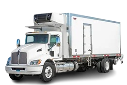
Compared with passenger cars, commercial vehicles often have longer cable routes and more “electrical neighbors” along the path—auxiliary lighting, PTO equipment, refrigeration units, telematics add-ons, and aftermarket devices. In practice, this increases exposure to conducted and radiated interference.
LVDS links are attractive in this context because they are designed around differential noise rejection and low-EMI behavior, aligning with the EMC reality of heavy vehicles.
Supports higher-definition video transport
Modern commercial-vehicle vision systems increasingly rely on higher-resolution sensors for wider fields of view and better detail. Compared with legacy composite video, LVDS-style digital transport is better aligned with HD camera pipelines because it carries digital image data without the composite-encoding limitations of CVBS.
In practice, LVDS links commonly show up in architectures used for digital mirror systems, side/rear cameras, and multi-camera monitoring where the system needs consistent image quality across multiple channels.
Digital transport fits how camera systems are actually used
Many commercial-vehicle camera systems do more than show a picture. They can feed recorders, support overlays (guidelines, warnings), and integrate into driver-assistance or mirror-replacement architectures. Those downstream functions are typically digital, so transporting video in digital form reduces the need for repeated analog-to-digital conversions in the signal chain.
Provides low-latency video transport
From a pure transport perspective, LVDS-style links are often chosen because they can move video data over the cable with very little added delay. They don’t depend on heavy compression or network-style buffering, so the transport stage can stay simple.
It’s important to be precise: total end-to-end latency still depends on the camera sensor readout, ISP processing, overlays, and the display path. But keeping the video link itself straightforward helps system designers avoid introducing extra delay in the wiring stage.
Video links often need control and diagnostics, too
Even in “just camera + monitor” deployments, systems still need configuration, status, and diagnostics. LVDS-style camera links are commonly paired with architectures that can carry video plus a bidirectional control channel, reducing separate wiring.
LVDS Digital Video vs. Analog Video (CVBS/AHD)
Analog video remains common in legacy and retrofit-friendly deployments, but the link behavior is different.
|
Dimension |
LVDS Digital Video |
Analog Video (CVBS / AHD) |
|---|---|---|
|
What travels on the wire |
Digital data using low-voltage differential signaling |
An analog waveform over coax (CVBS), or analog HD-over-coax families (e.g., AHD) |
|
Susceptibility to visible interference |
Differential reception improves common-mode noise rejection; LVDS is associated with reduced EMI concerns (see TI’s discussion in the LVDS EMI application note) |
Interference can show up directly as image noise, rolling lines, or loss of detail because the signal itself is an analog waveform |
|
Latency in the transport stage |
Typically designed to keep transport delay low because it carries image data directly over a point-to-point link; total latency depends on the full camera + display pipeline |
Often low in simple camera→monitor paths; if the system requires digitization, processing, or conversion stages, overall latency can increase |
|
Image characteristics |
No composite encoding artifacts; image fidelity depends on the sensor and the digital link design |
CVBS is a composite baseband format with inherent limitations; Analog Devices summarizes composite/CVBS fundamentals in Video Basics |
|
System integration |
Naturally aligns with digital processing pipelines (recording, analytics, CMS/ADAS integration) |
Typically requires analog decoding and A/D conversion before digital processing |
|
What the harness may carry besides video |
Often video plus control/diagnostics (when used in SerDes-style links) |
Usually video-only; control is separate or limited |
Note: CVBS vs LVDS is ultimately a comparison between analog baseband transport and differential digital signaling; real-world performance depends on the full architecture, components, and EMC design.
Key Takeaways
-
LVDS video is a digital video link built around low-voltage differential signaling.
-
It’s widely used in commercial-vehicle camera systems because differential signaling and low swing help handle long harness runs and harsh EMC conditions.
-
Analog formats like CVBS carry a baseband waveform that can expose interference as visible artifacts.
-
In modern systems, LVDS-style video transport often appears inside automotive camera SerDes links that carry video plus control over a single cable.
Conclusion
LVDS is best understood as a physical-layer signaling approach that helps carry digital video reliably in harsh vehicle environments. It’s not the only factor that determines image quality or end-to-end delay, but it’s a common foundation for modern camera architectures that need stable performance across longer harness runs.
When evaluating a camera link for commercial vehicles, it helps to separate the goals—HD image transport, EMC robustness, harness complexity, and latency—and then choose an architecture (LVDS, SerDes, or analog) that matches the full system requirements.